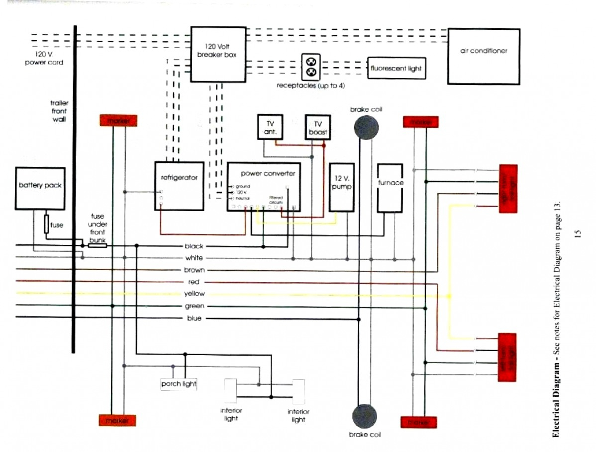

Source: Calibration the voltmeter is calibrated at the factory and recalibration should never be necessary. Meter wiring diagrams for low voltage meter stations for in whangarei and kaipara. Source: Print the wiring diagram off and use highlighters to be able to trace the routine. If you want to use this meter, you need to purchase a 100a/75mv shunt. The voltage wire connects directly to the service wire in this example. 1 run a 10 wire from the bat terminal on the alternator to the ammeter. It shows how the electrical wires are interconnected and can also show where fixtures and components may be connected to the system. Power supply+ black line (thick): Source: Source: Vacant or buck circuit (module) negative red line (thin): Com, common measuring red line (thick): Source: In the center of this diagram following the blue wire again this is an either or connection. Here is the wiring instructions for the dc 100v 10a meter: Source:

Assortment of volt amp meter wiring diagram. Source: ġ run a 10 wire from the bat terminal on the alternator to the ammeter. In the diagram above, the wire colours shown in brackets refer to model tc0002. Source: It shows how the electrical wires are interconnected and can also show where fixtures and components may be connected to the system. And then wiring it according to the wiring diagram we sent to you before. Com, common measuring red line (thick): Source: In the diagram above, the wire colours shown in brackets refer to model tc0002.

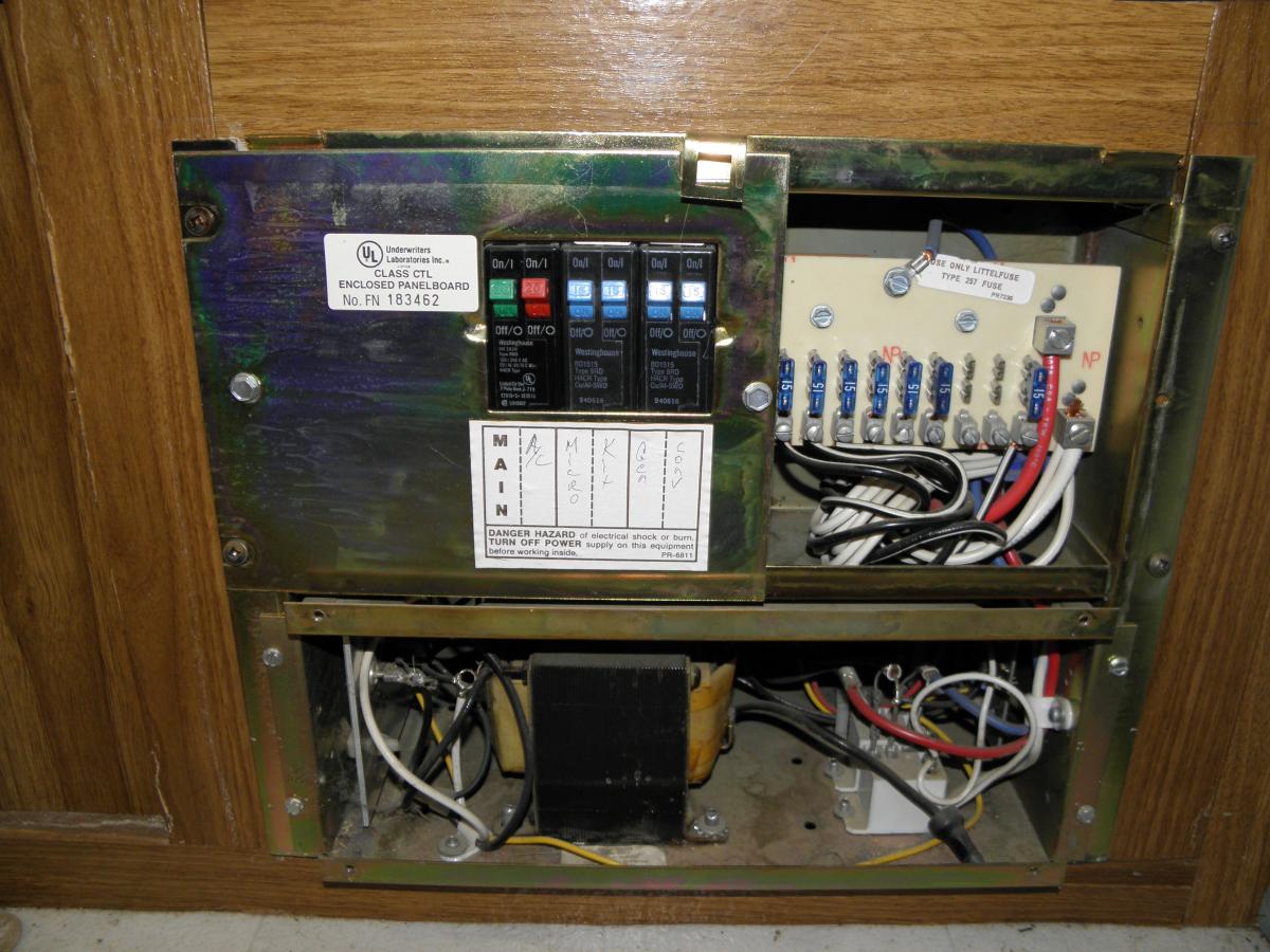
Connect phase to terminal m and neutral to terminal v. Use one of the wires that you found in the wiring harness and cut it between the steering column and connector in the dash. Pw+, measuring terminal voltage input positive yellow line (thick): When you measure the voltage between these 2 wires you will get 120 volts, or 230 volts for those systems not in the u.s. Vacant or buck circuit (module) negative red line (thin): Source: You will have 1 hot wire (commonly black or red) and a neutral wire (usually white). Progressive Dynamics Power Converter Wiring Diagram from 8 mm2 no mark wire size: Meter wiring diagrams for low voltage meter stations for in whangarei and kaipara. As you see in the above connection diagram, first make a short between m and c terminal. You can connect the wire to the left center terminal or the bottom center terminal. The Natures Head one should be 2.5 or 3, they had a 1 amp that blew on Day 2.The mistake was probably due to a simple failure to read the installation manual, it is clearly listed there.Voltage Meter Wiring Diagram. I consider it to be an unacceptable shortcut on their part foe a premium trailer. I am less than impressed with the choice of this unit for an Oliver when there are better marine grade units out there. You can use a set of narrow tipped needle nose pliers, and you could do it with power connected if you tape the tips and are brave like me, but it would be best to disconnect power entirely. I had intermittent fridge operation due to this problem.Ĭheck EVERY single fuse by carefully removing and reinstalling it straight! If one fuse is loose, tighten the clip by gently squeezing the little ears together to make a narrower gap. The fuse clips are very weak, and if you apply any side force to the fuse while inserting it, the ears can spread and then you have a poor connection. This photo shows the edge of the new module that can be seen with the front panel removed from the power center.Īgain, the charger will normally make a faint hum but if you have a loud noise coming from your converter there is a fix available. This photo shows the edge of the old module that can be seen with the front panel removed from the power center. The new larger module fit in the space where the smaller old module had been. The following picture shows the old and new modules side by side on my work bench. I called Progressive Dynamics and told them what was happening and they immediately said that they were aware of the problem and would send me a new converter module. KountryKamper listened to it at the rally and told me some things to try but I couldn’t get the noise to stop. The instant anything was switched on the noise would either change pitch or completely quit. The charger will normally make a faint hum, but this was a loud noise. I had a noise coming from my PD4060K Power Control Center only when plugged in to shore power, with the charger in storage mode at 13.2 volts and with nothing on in the camper.


 0 kommentar(er)
